一、單臂路由器
1、作用:實現不同vlan間通信
2、子接口:路由器的物理接口可以被劃分成多個邏輯接口,每個子接口對應一個vlan網段的網關
3、vlan標籤的封裝結構
全局:interface f0/0.1
encapsulation dot1Q 2 2和0.1是可變的。
4、單臂路由的缺陷:單筆容易形成網絡瓶頸,子接口依託於我錄接口,應用不靈活。vlan間轉發需要查看路由表,嚴重浪費設備資源。
二、三層交換技術
1、使用三層交換技術實現vlan間通信:三層交換=二層交換+三層轉發
2、基於CEF的快速轉發:主要包含兩個轉發用的信息表:
轉發信息庫FIB:FIB類似於路由表,包含路由表中轉發信息的鏡像。當網絡的拓撲發生變化時,路由表將被更新,而FIB也將隨之變化。
鄰接關係表:沒個FIB條目,鄰接關係表中都包含相應的第2層地址。
3、虛擬接口SVI:三層交換機上配置的vlan接口爲虛接口。
4、三層交換機的配置:在三層交換機啓用路由功能;全局:ip routing;
配置虛擬接口的IP地址:全局:interface vlan 2;ip address 192.168.2.1 255.255.255.0;no shutdown
三層交換機上配置trunk並制定接口封裝爲802.1q。接口模式:switchport trunk encapsulation dot1q ;switchport mode trunk
5、配置路由接口:進入接口:no switchport
三、動態路由
1、動態路由的特點:優點是減少了管理任務;缺點是佔用了網絡帶寬。
2、按照路由執行的算法,動態路由協議的分類:距離矢量路由協議:依據從源網絡到目標網絡所經過的路由器的個數選擇路由。(RIP、IPRP)
綜合考慮從源網絡到目標網絡的各條路徑的情況選擇路由。OSPE、IS-IS
3、RIP路由協議:是距離-矢量路由選擇協議;RIP度量值爲跳數,最大條數爲25跳。16跳路爲不可達,
RIT更新時間:每個20s發送路由更新消息,UDP520端口》發送整個路由表信息。
4、RIPV1與ROPV2的區別
RIPV1 RIPV2
有類路由協議 無類路由協議
廣播更新 組播更新(224.0.0.9)
不支持VLSM 支持VLSM
自動路由彙總,不可關閉 自動彙總可關閉,可手工彙總
更新的過程中不攜帶子網信息 更新的過程中攜帶子網信息
5、RIPV2的配置
全局:router rip ;version 2;no auto-summary(關閉路由彙總)
network 主網絡ID不需要子網掩碼
show ip int br
rip最多十五跳,十六跳不可達
實驗一
實驗名稱:實現三個路由器通過rip連接能夠通
實驗過程:
步驟1:配置基本環境
首先打開cisco packet tracer,購買三個路由器,兩臺主機。
並配置相應的IP段,如下圖。
進入router6輸入以下命令:
Router>ena
Router#conf t
Enter configuration commands, one per line. End with CNTL/Z.
Router(config)#router rip
Router(config-router)#version 2
Router(config-router)#no auto-summary
Router(config-router)#network 192.168.1.0
Router(config-router)#network 192.168.2.0
Router(config-router)#
進入router7輸入以下
Router>enable
Router#configure terminal
Enter configuration commands, one per line. End with CNTL/Z.
Router(config)#router rip
Router(config-router)#version 2
Router(config-router)#no auto-summary
Router(config-router)#network 192.168.2.0
Router(config-router)#network 192.168.3.0
Router(config-router)#
進入router8
Router>enable
Router#
Router#conf t
Enter configuration commands, one per line. End with CNTL/Z.
Router(config)#router rip
Router(config-router)#version 2
Router(config-router)#no auto-summary
Router(config-router)#network 192.168.3.0
Router(config-router)#network 192.168.4.0
Router(config-router)#
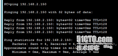
兩臺主機之間是可以ping通的
實驗二
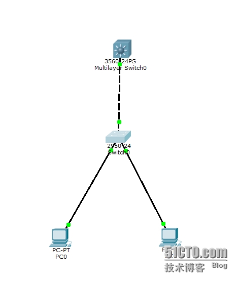
實驗名稱:三層交換機實現DHCP自動獲取
實驗過程
步驟1:配置基本環境
如下圖
打開二層交換機輸入
witch#
Switch#vlan database
% Warning: It is recommended to configure VLAN from config mode,
as VLAN database mode is being deprecated. Please consult user
documentation for configuring VTP/VLAN in config mode.
Switch(vlan)#vlan 2 name caiwu
VLAN 2 added:
Name: caiwu
Switch(vlan)#vlan 3 name renshi
VLAN 3 added:
Name: renshi
Switch(vlan)#exit
APPLY completed.
Exiting....
Switch#conf t
Enter configuration commands, one per line. End with CNTL/Z.
Switch(config)#int f0/1
Switch(config-if)#switchport access vlan 2
Switch(config-if)#int f0/2
Switch(config-if)#switchport access vlan 3
Switch(config-if)#end
Switch#
%SYS-5-CONFIG_I: Configured from console by console
Switch#show vlan
VLAN Name Status Ports
---- -------------------------------- --------- -------------------------------
1 default active Fa0/3, Fa0/4, Fa0/5, Fa0/6
Fa0/7, Fa0/8, Fa0/9, Fa0/10
Fa0/11, Fa0/12, Fa0/13, Fa0/14
Fa0/15, Fa0/16, Fa0/17, Fa0/18
Fa0/19, Fa0/20, Fa0/21, Fa0/22
Fa0/23, Fa0/24
2 caiwu active Fa0/1
3 renshi active Fa0/2
接下來爲二層交換機和三層交換機的線路配置中繼鏈路
Switch#
Switch#conf t
Enter configuration commands, one per line. End with CNTL/Z.
Switch(config)#int f0/24
Switch(config-if)#switchport mode trunk
Switch(config-if)#
%LINEPROTO-5-UPDOWN: Line protocol on Interface FastEthernet0/24, changed state to down
%LINEPROTO-5-UPDOWN: Line protocol on Interface FastEthernet0/24, changed state to up
Switch(config-if)#
步驟2:配置三層交換機
Switch>
Switch>enable
Switch#vlan database
% Warning: It is recommended to configure VLAN from config mode,
as VLAN database mode is being deprecated. Please consult user
documentation for configuring VTP/VLAN in config mode.
Switch(vlan)#vlan 2 name caiwu
VLAN 2 added:
Name: caiwu
Switch(vlan)#vlan 3 name renshi
VLAN 3 added:
Name: renshi
Switch(vlan)#exit
APPLY completed.
Exiting....
Switch(config)#int vl 2
Switch(config-if)#
%LINK-5-CHANGED: Interface Vlan2, changed state to up
%LINEPROTO-5-UPDOWN: Line protocol on Interface Vlan2, changed state to up
Switch(config-if)#ip address 192.168.1.254 255.255.255.0
Switch(config-if)#no shutdown
Switch(config-if)#exit
Switch(config)#int vl 3
Switch(config-if)#
%LINK-5-CHANGED: Interface Vlan3, changed state to up
%LINEPROTO-5-UPDOWN: Line protocol on Interface Vlan3, changed state to up
Switch(config-if)#ip address 192.168.2.254 255.255.255.0
Switch(config-if)#no shutdown
Switch(config-if)#exit
Switch(config)#int f0/24
Switch(config-if)#switchport trunk encapsulation dot1q
Switch(config-if)#switchport mode trunk
Switch(config-if)#
三層交換機配置完成,下面爲三層交換機下的vlan配置dhcp自動獲取
步驟3:
Switch(config)#ip dhcp pool vlan1
Switch(dhcp-config)#network 192.168.1.0 255.255.255.0
Switch(dhcp-config)#default-router 192.168.1.254
Switch(dhcp-config)#dns-server 202.106.0.20
Switch(dhcp-config)#ip dhcp pool vlan2
Switch(dhcp-config)#network 192.168.2.0 255.255.255.0
Switch(dhcp-config)#dns-server 202.106.0.20
Switch(dhcp-config)#default-router 192.168.2.254
Switch(dhcp-config)#
這樣就爲兩和vlan配好了各自的dhcp
下面爲各自網段進行IP限制
Switch(config)#ip dhcp excluded-address 192.168.1.1 192.168.1.149
Switch(config)#ip dhcp excluded-address 192.168.1.156 192.168.1.254
Switch(config)#ip dhcp excluded-address 192.168.2.1 192.168.2.149
Switch(config)#ip dhcp excluded-address 192.168.2.156 192.168.2.254
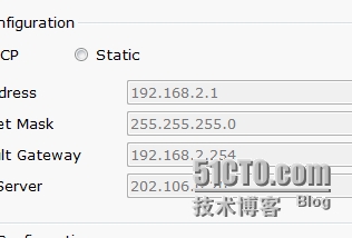
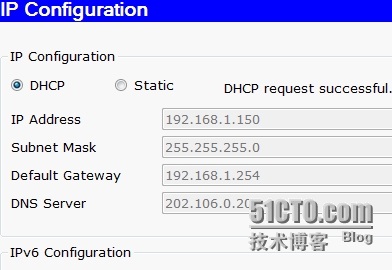
如圖
至此,實驗完成
實驗結果:今天的實驗除了需要很熟練的手法意外,還得需要熟練以前的所有基礎內容,應該注意以前的知識的融合。同時要明白整個實驗的理論體系。


