


這是我這段時間在LaTex中繪圖的一些例子,發佈在這裏一方面是備忘,另一方面是與大家交流。示例持續增加中……
環境:Ubuntu 16.04 64位桌面版
工具:TeXstudio
1. 非常簡單的一個程序結構圖
完整代碼如下:
% 51CTO陸巍的博客
\documentclass[oneside, AutoFakeBold]{article}

\usepackage{geometry}          % 用於頁面設置
% 設置爲A4紙,並按照MSOffice的默認尺寸設置四周邊距
\geometry{
  a4paper,
  left = 3.17cm,
  right = 3.17cm,
  top = 2.54cm,
  bottom = 2.54cm
}

% 顏色支持
\usepackage[dvipsnames, svgnames, x11names]{xcolor}

% 漢字支持
\usepackage{xeCJK}
% 設置字體。注意順序,第一個定義的就是默認字體
\setCJKfamilyfont{song}{方正書宋簡體}
\newcommand{\song}{\CJKfamily{song}}
\setCJKfamilyfont{kaiti}{方正楷體簡體}
\newcommand{\kaiti}{\CJKfamily{kaiti}}
\setCJKfamilyfont{heiti}{方正黑體簡體}
\newcommand{\heiti}{\CJKfamily{heiti}}

% 繪圖支持
\usepackage{tikz}
\usetikzlibrary{arrows}
% 支持繪製UML
\usepackage[simplified]{pgf-umlcd}

% 設置斷字參數,數值越大,出現斷字的情況越少
\hyphenpenalty = 1000

% ------------------ 開始 -------------------

\begin{document}
  \section{示例001}
  % 定義圖形基本形狀
  \tikzstyle{process1} = [rectangle, minimum width = 3cm, minimum height = 1cm, text centered, draw = black, fill = White]
  \tikzstyle{arrow} = [thick, --, >=stealth]
  \begin{center}
    \begin{tikzpicture}[node distance = 2cm]
      \node(copy)[process1]{Copy};
      \node(keyboard)[process1, below left of = copy, xshift = -1cm, yshift = -1cm]{Read Keyboard};
      \node(printer)[process1, below right of = copy, xshift = 1cm, yshift = -1cm]{Write Printer};

      \draw(keyboard.north) -- ++(0, 0.9) -| (printer.north);
      \draw(copy.south) -- ++(0, -0.5);
      \draw[thick, o->] (-3.2, -1.7) -- (-3.2, -1)node[below left, xshift = -0.3cm]{char};
      \draw[thick, o->] (3.2, -1) -- (3.2, -1.7)node[above right, xshift = 0.3cm]{char};
    \end{tikzpicture}
    \\[0.4cm]\heiti 圖7.1 Copy程序結構圖
  \end{center}
\end{document}
效果如下: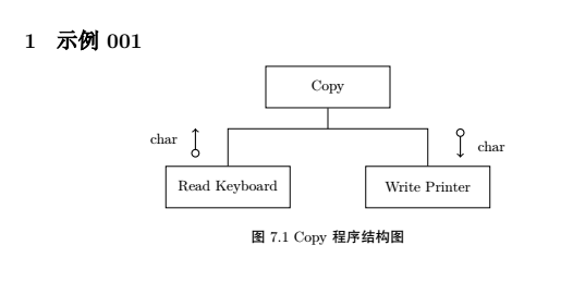
說明:
1) 注意帶圓圈箭頭的繪製方法:o->。是字母o,不是數字0。
2) 注意兩條沒有直接連接方框的箭頭繪製,在上面加文字時需要在文字前面有node的相關設置。
2. 簡單UML圖一
代碼如下:
% 51CTO陸巍的博客
\section{示例002}
  \begin{center}
    \begin{tikzpicture}
      \begin{class}[text width = 2.8cm, text height = 0.35cm, text depth = 1.0cm]{Computational Geometry Application}{-5, 0}
      \end{class}

      \begin{class}[text width = 2.8cm, text height = 0.6cm, text depth = 0.75cm]{Graphical Application}{0, 0}
      \end{class}

      \begin{class}[text width = 2.8cm]{Geometry Rectangle}{-5, -3}
        \operation{+ area() : double}
      \end{class}

      \begin{class}[text width = 2.8cm, text height = 0.5cm, text depth = 0.25cm]{Rectangle}{0, -3}
        \operation{+ draw()}
      \end{class}

      \begin{class}[text width = 2.8cm, text height = 0.8cm, text depth = 0.55cm]{GUI}{5, -3}
      \end{class}

      \unidirectionalAssociation{Computational Geometry Application}{}{}{Geometry Rectangle}
      \unidirectionalAssociation{Graphical Application}{}{}{Rectangle}
      \unidirectionalAssociation{Rectangle}{}{}{Geometry Rectangle}
      \unidirectionalAssociation{Rectangle}{}{}{GUI}
      \draw [umlcd style inherit line, ->] (Graphical Application) -| (GUI);
    \end{tikzpicture}
    \\[0.4cm]\heiti 圖8.2 分離的職責\song
  \end{center}
效果如下:
說明:
1) 注意讓框中文字垂直居中的方式:用text height與text depth來調節。text height可以簡單地視爲文字與上邊框的距離,text depth可以簡單地視爲文字與下邊框的距離。
2) 這個例子的文件頭部分的內容與上一個例子是一樣的,以下的例子也是如此。
3. 簡單UML圖二
代碼如下:
\section{示例003}
  \begin{center}
    \begin{tikzpicture}
      \begin{interface}[text width = 2.4cm]{Data Channel}{-2.5, 0}
        \operation{+send(: char)}
        \operation{+secv() : char}
      \end{interface}

      \begin{interface}[text width = 2.6cm, text height = 0.5cm, text depth = 0.6cm]{Connection}{2.5, 0}
        \operation{+dial(pno:String)}
        \operation{+hangup()}
      \end{interface}

      \begin{class}[text width = 3.0cm]{Modem Implementation}{0, -3}
      \end{class}

      \draw [umlcd style implement line, -open triangle 45] (Modem Implementation) -| (Data Channel);
      \draw [umlcd style implement line, -open triangle 45] (Modem Implementation) -| (Connection);
    \end{tikzpicture}
    \\[0.4cm]\heiti 圖8.3 分離的Modem接口\song
  \end{center}
效果如下:
說明:
這裏只是要注意箭頭的畫法:umlcd style implement line, -open triangle 45。更多的箭頭類型請看箭頭類型 。