


如何解決路由黑洞?
1、全互聯(全互聯的意思就是在一個AS內的所有的BGP路由器全部都建立我們Establish的關係)
2、RR(反射器)
3、聯盟(一般用的不多)
4、將BGP路由引入到IGP,從而保證IGP與BGP的同步。但是,因爲Internet上的BGP路由數量十分龐大,一旦引入到IGP,會給IGP路由器帶來巨大的處理和存儲負擔,如果路由器負擔過重,則可能癱瘓 不建議
5、MPLS技術解決路由黑洞問題
解決方法1.全互聯
在一個AS內的所有的BGP路由器全部都建立我們Establish的關係
R2 R3 R4之間的loopback接口之間相互建立IBGP的關係
R2的配置
#
bgp 200
 router-id 2.2.2.2
 peer 3.3.3.3 as-number 200
 peer 3.3.3.3 connect-interface LoopBack0
 peer 4.4.4.4 as-number 200
 peer 4.4.4.4 connect-interface LoopBack0
 peer 192.168.12.1 as-number 100
 #
 ipv4-family unicast
  undo synchronization
  peer 3.3.3.3 enable
  peer 3.3.3.3 next-hop-local
  peer 4.4.4.4 enable
  peer 4.4.4.4 next-hop-local
#
R3的BGP配置
#
bgp 200
 peer 2.2.2.2 as-number 200
 peer 2.2.2.2 connect-interface LoopBack0
 peer 4.4.4.4 as-number 200
 peer 4.4.4.4 connect-interface LoopBack0
 #
 ipv4-family unicast
  undo synchronization
  peer 1.1.1.1 enable
  peer 4.4.4.4 enable
#
R4的BGP配置
#
bgp 200
 router-id 4.4.4.4
 peer 2.2.2.2 as-number 200
 peer 2.2.2.2 connect-interface LoopBack0
 peer 3.3.3.3 as-number 200
 peer 3.3.3.3 connect-interface LoopBack0
#
 ipv4-family unicast
  undo synchronization
  peer 2.2.2.2 enable
  peer 2.2.2.2 next-hop-local
  peer 3.3.3.3 enable
  peer 3.3.3.3 next-hop-local
#
在R3上檢查IBGP的關係
[R3]display bgp peer

 BGP local router ID : 192.168.34.3
 Local AS number : 200
 Total number of peers : 2                Peers in established state : 2

  Peer            V          AS  MsgRcvd  MsgSent  OutQ  Up/Down       State PrefRcv

  2.2.2.2         4         200        3        2     0 00:00:02 Established       1
  4.4.4.4         4         200        5        5     0 00:02:30 Established       1
[R3]
在R3上面看下是否能夠學習到關係1.1.1.1和5.5.5.5的路由
[R3]display bgp routing-table

 BGP Local router ID is 192.168.34.3
 Status codes: * - valid, > - best, d - damped,
               h - history,  i - internal, s - suppressed, S - Stale
               Origin : i - IGP, e - EGP, ? - incomplete

 Total Number of Routes: 2
      Network            NextHop        MED        LocPrf    PrefVal Path/Ogn

 *>i  1.1.1.1/32         2.2.2.2         0          100        0      100i
 *>i  5.5.5.5/32         4.4.4.4         0          100        0      300i
[R3]
在R5上面訪問R1
<R5>ping -a 5.5.5.5 1.1.1.1
  PING 1.1.1.1: 56  data bytes, press CTRL_C to break
    Reply from 1.1.1.1: bytes=56 Sequence=1 ttl=252 time=80 ms
    Reply from 1.1.1.1: bytes=56 Sequence=2 ttl=252 time=40 ms
    Reply from 1.1.1.1: bytes=56 Sequence=3 ttl=252 time=60 ms
    Reply from 1.1.1.1: bytes=56 Sequence=4 ttl=252 time=40 ms
    Reply from 1.1.1.1: bytes=56 Sequence=5 ttl=252 time=50 ms

  --- 1.1.1.1 ping statistics ---
    5 packet(s) transmitted
    5 packet(s) received
    0.00% packet loss
    round-trip min/avg/max = 40/54/80 ms
缺點:
BGP 200裏面的設備越多 需要建立IBGP的數量也就越多 可以考慮用反射器解決
解決方法2.RR
刪除上面BGP R2 R3 R4的BGP配置
R3設備爲反射器 R2和R4設備爲客戶端 反射器和客戶端之間IBGP關係就可以 客戶端和客戶端之間不需要建立起任何關係
優點:減少AS 200裏面的IBGP的數量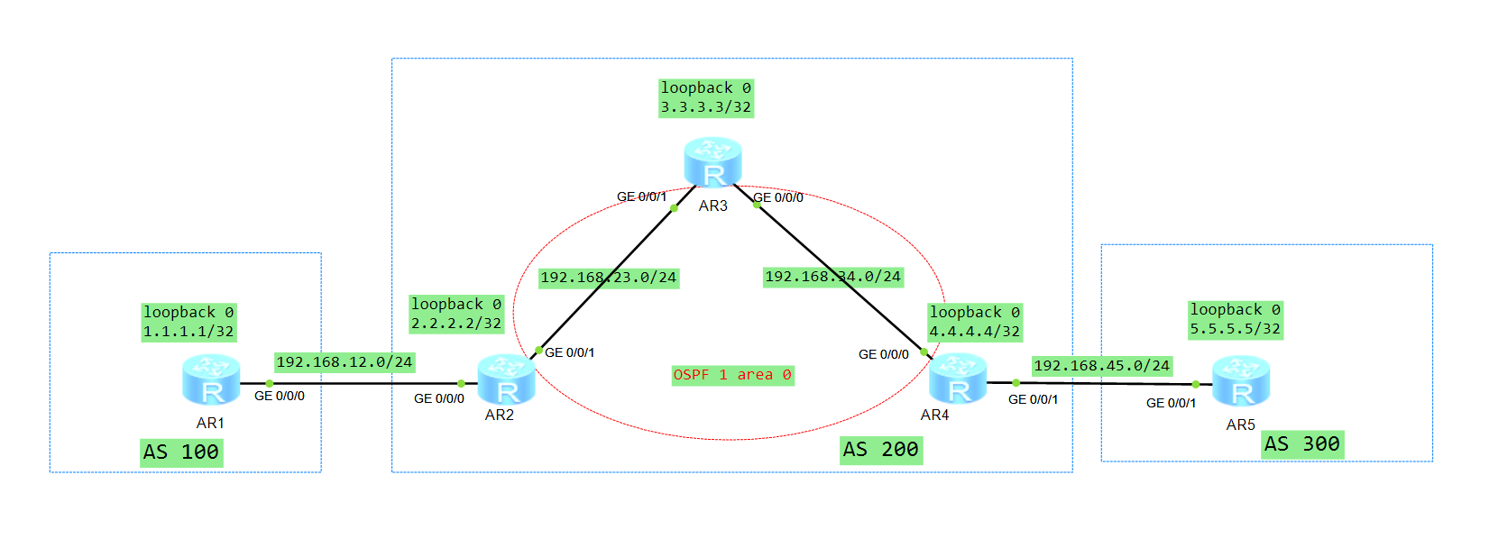
R2的配置
#
bgp 200
 router-id 2.2.2.2
 peer 3.3.3.3 as-number 200     //R2和反射器建立IBGP關係
 peer 3.3.3.3 connect-interface LoopBack0
#
 ipv4-family unicast
  undo synchronization
  peer 3.3.3.3 enable
  peer 3.3.3.3 next-hop-local
#
R4的配置
#
bgp 200
 router-id 4.4.4.4
 peer 3.3.3.3 as-number 200     //R2和反射器建立IBGP關係
 peer 3.3.3.3 connect-interface LoopBack0
 peer 192.168.45.5 as-number 300
 #
 ipv4-family unicast
  undo synchronization
  peer 3.3.3.3 enable
  peer 3.3.3.3 next-hop-local
#
R3的配置
#
bgp 200
 peer 2.2.2.2 as-number 200
 peer 2.2.2.2 connect-interface LoopBack0
 peer 4.4.4.4 as-number 200
 peer 4.4.4.4 connect-interface LoopBack0
 #
 ipv4-family unicast
  undo synchronization
  peer 2.2.2.2 enable
  peer 2.2.2.2 reflect-client       //R2反射器和客戶端建立IBGP關係
  peer 4.4.4.4 enable
  peer 4.4.4.4 reflect-client       //R2反射器和客戶端建立IBGP關係
#
在R5上面訪問R1
<R5>ping -a 5.5.5.5 1.1.1.1
  PING 1.1.1.1: 56  data bytes, press CTRL_C to break
    Reply from 1.1.1.1: bytes=56 Sequence=1 ttl=252 time=80 ms
    Reply from 1.1.1.1: bytes=56 Sequence=2 ttl=252 time=40 ms
    Reply from 1.1.1.1: bytes=56 Sequence=3 ttl=252 time=60 ms
    Reply from 1.1.1.1: bytes=56 Sequence=4 ttl=252 time=40 ms
    Reply from 1.1.1.1: bytes=56 Sequence=5 ttl=252 time=50 ms

  --- 1.1.1.1 ping statistics ---
    5 packet(s) transmitted
    5 packet(s) received
    0.00% packet loss
    round-trip min/avg/max = 40/54/80 ms
解決方法3.聯盟
刪除RR的配置 我們可以將AS 200拆成3個子的AS 分別爲1000 2000 3000AS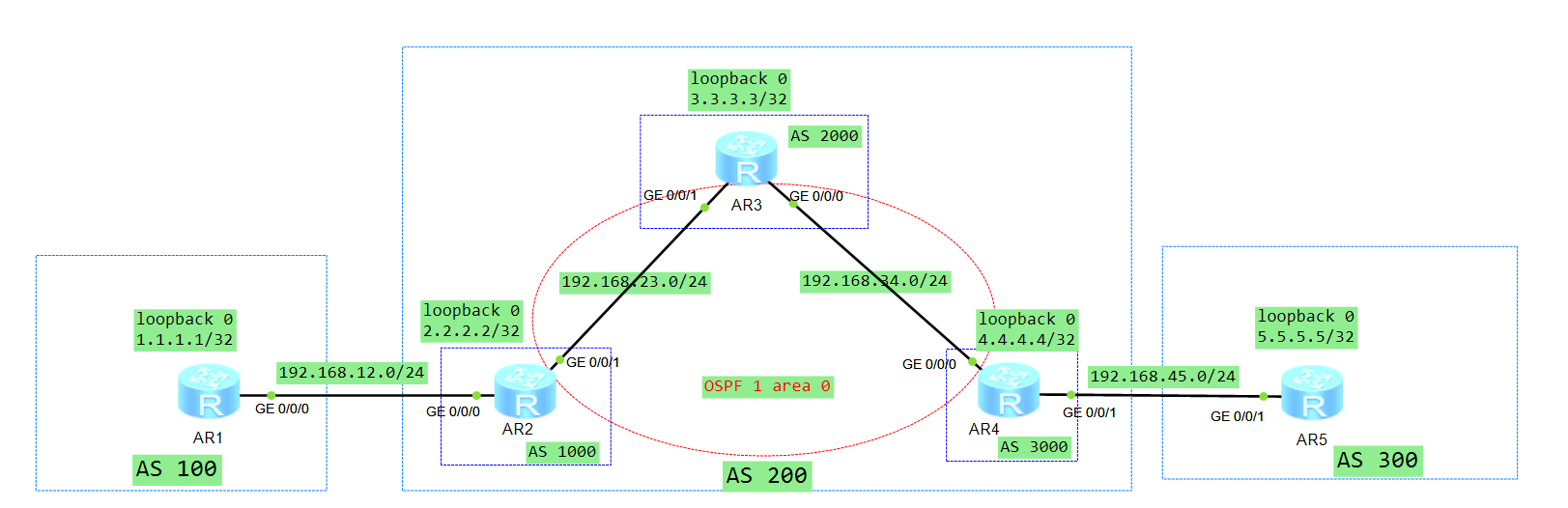
在R2這邊的配置
#
bgp 1000        //R2上面直接配置子AS 1000
 router-id 2.2.2.2
 confederation id 200   //R2對外還是宣稱在AS 200裏面
 confederation peer-as 2000     //指定和對端子AS 2000建立EBGP關係
 peer 192.168.12.1 as-number 100
 peer 192.168.23.3 as-number 2000
 #
 ipv4-family unicast
  undo synchronization
  peer 192.168.12.1 enable
  peer 192.168.23.3 enable
  peer 192.168.23.3 next-hop-local  //在AS 200內部雖然R2和R3是EBGP關係  但是畢竟R2 和R3在一個AS 200當中  R2從R1學習到的路由  發給R3的時候下一跳還是不變化  所以需要敲如下命令實現R2發給R3的時候下一跳爲R2本身
#
在R3這邊的配置
#
bgp 2000
 confederation id 200
 confederation peer-as 1000 3000
 peer 192.168.23.2 as-number 1000
 peer 192.168.34.4 as-number 3000
 #
 ipv4-family unicast
  undo synchronization
  peer 192.168.23.2 enable
  peer 192.168.34.4 enable
#
在R4這邊的配置
#
bgp 3000
 confederation id 200
 confederation peer-as 2000
 peer 192.168.34.3 as-number 2000
 peer 192.168.45.5 as-number 300
 #
 ipv4-family unicast
  undo synchronization
  peer 192.168.34.3 enable
  peer 192.168.34.3 next-hop-local
  peer 192.168.45.5 enable
#
檢查R2 R3 R4的BGP關係
<R2>display bgp peer

 BGP local router ID : 2.2.2.2
 Local AS number : 1000
 Total number of peers : 2                Peers in established state : 2

  Peer            V          AS  MsgRcvd  MsgSent  OutQ  Up/Down       State PrefRcv

  192.168.12.1    4         100       10       10     0 00:07:29 Established       1
  192.168.23.3    4        2000       20       18     0 00:08:53 Established       1
<R2>
[R3]display bgp peer
BGP local router ID : 192.168.34.3
Local AS number : 2000
Total number of peers : 2 Peers in established state : 2
Peer V AS MsgRcvd MsgSent OutQ Up/Down State PrefRcv
192.168.23.2 4 1000 18 21 0 00:09:00 Established 1
192.168.34.4 4 3000 13 21 0 00:08:17 Established 1
[R3][R4]display bgp peer
BGP local router ID : 192.168.34.4
Local AS number : 3000
Total number of peers : 2 Peers in established state : 2
Peer V AS MsgRcvd MsgSent OutQ Up/Down State PrefRcv
192.168.34.3 4 2000 20 13 0 00:08:21 Established 1
192.168.45.5 4 300 10 12 0 00:07:23 Established 1
[R4]檢查R2 R3 R4的路由
[R4]display bgp routing-table

 BGP Local router ID is 192.168.34.4
 Status codes: * - valid, > - best, d - damped,
               h - history,  i - internal, s - suppressed, S - Stale
               Origin : i - IGP, e - EGP, ? - incomplete

 Total Number of Routes: 2
      Network            NextHop        MED        LocPrf    PrefVal Path/Ogn

 *>i  1.1.1.1/32         192.168.23.2    0          100        0      (2000 1000) 100i
 *>   5.5.5.5/32         192.168.45.5    0                     0      300i
[R4]
[R3]display bgp routing-table
BGP Local router ID is 192.168.34.3
Status codes: * - valid, > - best, d - damped,
h - history, i - internal, s - suppressed, S - Stale
Origin : i - IGP, e - EGP, ? - incomplete
Total Number of Routes: 2
Network NextHop MED LocPrf PrefVal Path/Ogn
*>i 1.1.1.1/32 192.168.23.2 0 100 0 (1000) 100i
*>i 5.5.5.5/32 192.168.34.4 0 100 0 (3000) 300i
[R3]<R2>display bgp routing-table
BGP Local router ID is 2.2.2.2
Status codes: * - valid, > - best, d - damped,
h - history, i - internal, s - suppressed, S - Stale
Origin : i - IGP, e - EGP, ? - incomplete
Total Number of Routes: 2
Network NextHop MED LocPrf PrefVal Path/Ogn
*> 1.1.1.1/32 192.168.12.1 0 0 100i
*>i 5.5.5.5/32 192.168.34.4 0 100 0 (2000 3000) 300i
<R2>在R5上面訪問R1
<R5>ping -a 5.5.5.5 1.1.1.1
  PING 1.1.1.1: 56  data bytes, press CTRL_C to break
    Reply from 1.1.1.1: bytes=56 Sequence=1 ttl=252 time=80 ms
    Reply from 1.1.1.1: bytes=56 Sequence=2 ttl=252 time=40 ms
    Reply from 1.1.1.1: bytes=56 Sequence=3 ttl=252 time=60 ms
    Reply from 1.1.1.1: bytes=56 Sequence=4 ttl=252 time=40 ms
    Reply from 1.1.1.1: bytes=56 Sequence=5 ttl=252 time=50 ms

  --- 1.1.1.1 ping statistics ---
    5 packet(s) transmitted
    5 packet(s) received
    0.00% packet loss
    round-trip min/avg/max = 40/54/80 ms
缺點
聯盟的配置改動量特別大 不建議還割接的時候用這個方式
解決方法4. 將BGP路由引入到IGP
刪除聯盟的配置 將BGP路由引入到IGP裏面 在R2上引入和R4上面 將BGP路由引入到OSPF裏面
R2的配置
#
ospf 1 router-id 2.2.2.2
 import-route bgp
#
R4的配置
#
ospf 1 router-id 4.4.4.4
 import-route bgp
#
查看R3的路由表
<R3>display ip routing-table protocol ospf
Route Flags: R - relay, D - download to fib
------------------------------------------------------------------------------
Public routing table : OSPF
         Destinations : 4        Routes : 4

OSPF routing table status : <Active>
         Destinations : 4        Routes : 4

Destination/Mask    Proto   Pre  Cost      Flags NextHop         Interface

        1.1.1.1/32  O_ASE   150  1           D   192.168.23.2    GigabitEthernet0/0/1
        2.2.2.2/32  OSPF    10   1           D   192.168.23.2    GigabitEthernet0/0/1
        4.4.4.4/32  OSPF    10   1           D   192.168.34.4    GigabitEthernet0/0/0
        5.5.5.5/32  O_ASE   150  1           D   192.168.34.4    GigabitEthernet0/0/0

OSPF routing table status : <Inactive>
         Destinations : 0        Routes : 0
在R5上面訪問R1
<R5>ping -a 5.5.5.5 1.1.1.1
  PING 1.1.1.1: 56  data bytes, press CTRL_C to break
    Reply from 1.1.1.1: bytes=56 Sequence=1 ttl=252 time=80 ms
    Reply from 1.1.1.1: bytes=56 Sequence=2 ttl=252 time=40 ms
    Reply from 1.1.1.1: bytes=56 Sequence=3 ttl=252 time=60 ms
    Reply from 1.1.1.1: bytes=56 Sequence=4 ttl=252 time=40 ms
    Reply from 1.1.1.1: bytes=56 Sequence=5 ttl=252 time=50 ms

  --- 1.1.1.1 ping statistics ---
    5 packet(s) transmitted
    5 packet(s) received
    0.00% packet loss
    round-trip min/avg/max = 40/54/80 ms
思考如下:
能不能只在R2或者R4上面進行引入?會有什麼問題?如何解決?
解決方法5.MPLS技術
刪除上面引入的配置
在R2 R3 R4設備之間配置MPLS 和MPLS LDP協議 讓R5訪問R1的數據走2.5層進行轉發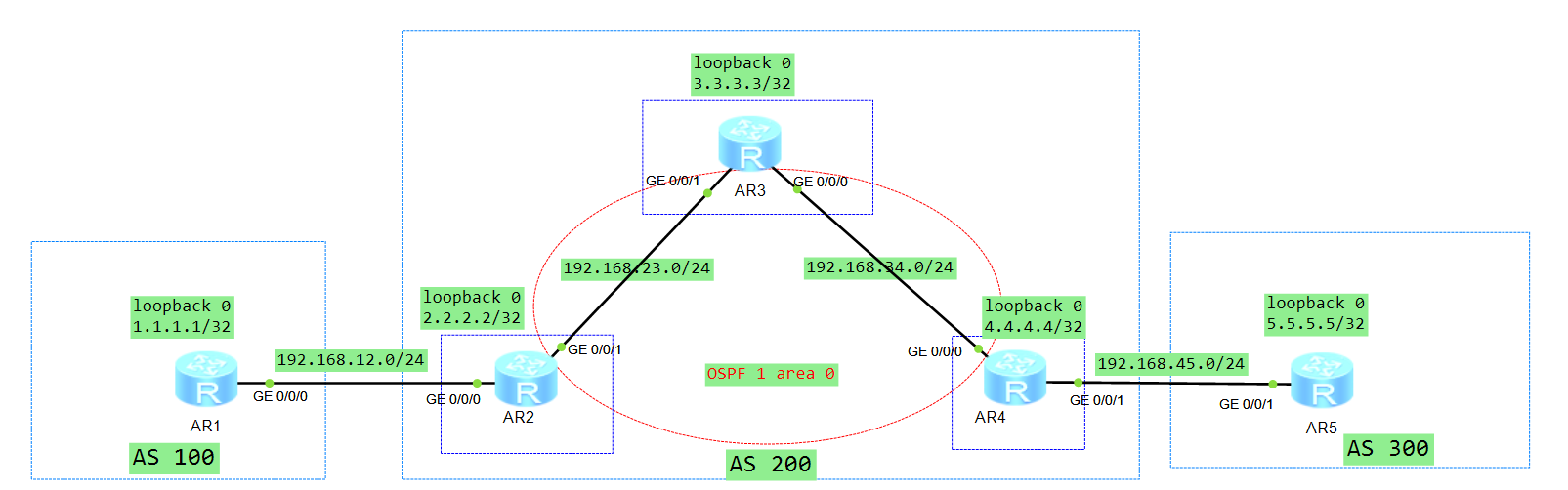
在R2上的配置
#
mpls lsr-id 2.2.2.2
#
mpls
#
mpls ldp
#
interface GigabitEthernet0/0/1
 mpls
 mpls ldp
#
在R3上的配置
#
mpls lsr-id 3.3.3.3
#
mpls
#
mpls ldp
#
interface GigabitEthernet0/0/1
 mpls
 mpls ldp
#
interface GigabitEthernet0/0/0
 mpls
 mpls ldp
#
在R4上的配置
#
mpls lsr-id 4.4.4.4
#
mpls
#
mpls ldp
#
interface GigabitEthernet0/0/0
 mpls
 mpls ldp
#
檢查LDP的關係
<R3>display mpls ldp session all

 LDP Session(s) in Public Network
 Codes: LAM(Label Advertisement Mode), SsnAge Unit(DDDD:HH:MM)
 A '*' before a session means the session is being deleted.
 ------------------------------------------------------------------------------
 PeerID             Status      LAM  SsnRole  SsnAge      KASent/Rcv
 ------------------------------------------------------------------------------
 2.2.2.2:0          Operational DU   Active   0000:00:04  17/17
 4.4.4.4:0          Operational DU   Passive  0000:00:03  16/16
 ------------------------------------------------------------------------------
 TOTAL: 2 session(s) Found.

<R3>
在R5上面訪問R1
<R5>ping -a 5.5.5.5 1.1.1.1
  PING 1.1.1.1: 56  data bytes, press CTRL_C to break
    Reply from 1.1.1.1: bytes=56 Sequence=1 ttl=252 time=80 ms
    Reply from 1.1.1.1: bytes=56 Sequence=2 ttl=252 time=40 ms
    Reply from 1.1.1.1: bytes=56 Sequence=3 ttl=252 time=60 ms
    Reply from 1.1.1.1: bytes=56 Sequence=4 ttl=252 time=40 ms
    Reply from 1.1.1.1: bytes=56 Sequence=5 ttl=252 time=50 ms

  --- 1.1.1.1 ping statistics ---
    5 packet(s) transmitted
    5 packet(s) received
    0.00% packet loss
    round-trip min/avg/max = 40/54/80 ms
注意:MPLS 虛擬私有網絡就是靠這種方式實現的