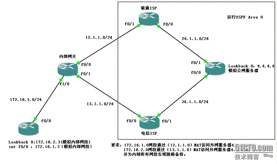
其他的配置就不上了,主要顯示內部網關route-map及NAT配置情況。
配置思路:
一、首先建立ACL過濾感興趣流量(供route-map調用)
access-list 10 permit 172.16.1.0 0.0.0.255
access-list 20 permit 172.16.2.0 0.0.0.255
二、建立route-map匹配列表及匹配動作(供NAT調用)
route-map 1 permit 10(1自定義只在本地有效,permit表示匹配,10表示列表第一項自定義)
match ip address 10(匹配ACL列表10的流量)
match interface FastEthernet 0/0(匹配端口F0/0,即向F0/0轉發)
route-map 2 permit 10
match ip address 20
match interface FastEthernet 0/1
route-map 3 permit 10
match ip address 10
route-map 4 permit 10
match ip address 20
--------------------------------------------------------------
以下route-map應用在網關設備入端口,優先於NAT中的route-map執行。
route-map test permit 10
match ip address 10
match interface FastEthernet 0/0
set interface FastEthernet 0/0(如上述match項匹配,即進行動作向F0/0端口轉發)
route-map test permit 20
match ip address 20
match interface FastEthernet 0/1
set interface FastEthernet 0/1
三、接口LAN應用route-maptest
interface FastEthernet 1/0
ip policy route-map test
四、配置NAT:
ip nat source route-map 1 interface FastEthernet 0/0 overload
ip nat source route-map 2 interface FastEthernet 0/1 overload
ip nat source route-map 3 interface FastEthernet 0/1 overload
ip nat source route-map 4 interface FastEthernet 0/0 overload
網關設備接口F0/0、F0/1接口模式分別使用:ip nat outside(注意:ip nat enable)
網關設備接口F1/0接口模式使用:ip nat inside即可。
五、默認路由和指向內網172.16.1.0網段的路由:
ip route 0.0.0.0 0.0.0.0 12.1.1.2
ip route 0.0.0.0 0.0.0.0 13.1.1.3
ip route 172.16.2.0 255.255.255.0 172.16.1.3此處路由主要是因爲Lookback0模擬內網網段。
到此,基本配置結束!
測試結果:
172.16.1.3ping4.4.4.4
*Oct3012:43:21.283:NAT*:s=172.16.1.3->12.1.1.1,d=4.4.4.4[45]
*Oct3012:43:21.367:NAT:s=4.4.4.4,d=12.1.1.1->172.16.1.3[45]
*Oct3012:43:21.443:NAT*:s=172.16.1.3->12.1.1.1,d=4.4.4.4[46]
*Oct3012:43:21.507:NAT:s=4.4.4.4,d=12.1.1.1->172.16.1.3[46]
*Oct3012:43:21.599:NAT*:s=172.16.1.3->12.1.1.1,d=4.4.4.4[47]
*Oct3012:43:21.663:NAT:s=4.4.4.4,d=12.1.1.1->172.16.1.3[47]
172.16.2.3ping4.4.4.4
*Oct3012:53:00.359:NAT*:s=172.16.2.3->13.1.1.1,d=4.4.4.4[50]
*Oct3012:53:00.415:NAT:s=4.4.4.4,d=13.1.1.1->172.16.2.3[50]
*Oct3012:53:00.487:NAT*:s=172.16.2.3->13.1.1.1,d=4.4.4.4[51]
*Oct3012:53:00.559:NAT:s=4.4.4.4,d=13.1.1.1->172.16.2.3[51]
*Oct3012:53:00.647:NAT*:s=172.16.2.3->13.1.1.1,d=4.4.4.4[52]
*Oct3012:53:00.743:NAT:s=4.4.4.4,d=13.1.1.1->172.16.2.3[52]
以上信息顯示實現數據分流的作用。
當網關設備F0/0接口出現故障後:172.16.1.3ping4.4.4.4的結果:
F0/0shutdown,172.16.1.3ping4.4.4.4
*Oct3013:05:58.815:NAT*:s=172.16.1.3->13.1.1.1,d=4.4.4.4[55]
*Oct3013:05:58.867:NAT:s=4.4.4.4,d=13.1.1.1->172.16.1.3[55]
*Oct3013:05:58.943:NAT*:s=172.16.1.3->13.1.1.1,d=4.4.4.4[56]
*Oct3013:05:59.051:NAT:s=4.4.4.4,d=13.1.1.1->172.16.1.3[56]
*Oct3013:05:59.111:NAT*:s=172.16.1.3->13.1.1.1,d=4.4.4.4[57]
*Oct3013:05:59.147:NAT:s=4.4.4.4,d=13.1.1.1->172.16.1.3[57]
從信息可以看出,172.16.1.3經過13.1.1.1訪問4.4.4.4,即備份線路生效。
如果將內部網關設備對端接口shutdown後,172.16.1.3ping4.4.4.4並不會選擇走13.1.1.1線路,可以看出此配置方法的不足之處。

